18. Spatial Cable Shape Finding
18.1 Function Introduction
This module calculates spatial ideal bridge completion cable shape, saddle positions, saddle preset amounts and free cable shape, single-span main cable spatial shape, etc. for suspension bridges based on analytical method. Main functions include:
- Spatial ideal bridge completion cable shape calculation for suspension bridges
- During bridge completion shape finding, side span balance control conditions can select longitudinal force/horizontal plane resultant force equality, anchor span balance control conditions can select horizontal plane resultant force/longitudinal force/cable force equality.
- Accurate spatial shape and cable force for each span main cable.
- Relative position of cable saddle and main cable.
- Accurately considering actual main cable shape length, unstressed length and elongation amount after considering spatial saddle internal curve shape.
- Stiffening beam design shape.
- Theoretical shape length and unstressed length, cutting length of hanger cables.
- Spatial cable shape and saddle preset amount calculation
- Consider temperature difference effect and free cable spatial shape with saddle reserved displacement
- Theoretical position of cable clamps
- Spatial saddle preset amount
18.2 Unit System and Coordinate System
Except for special explanations, the unit system regulations for this module are as follows: force (kN), length (m), angle (°).
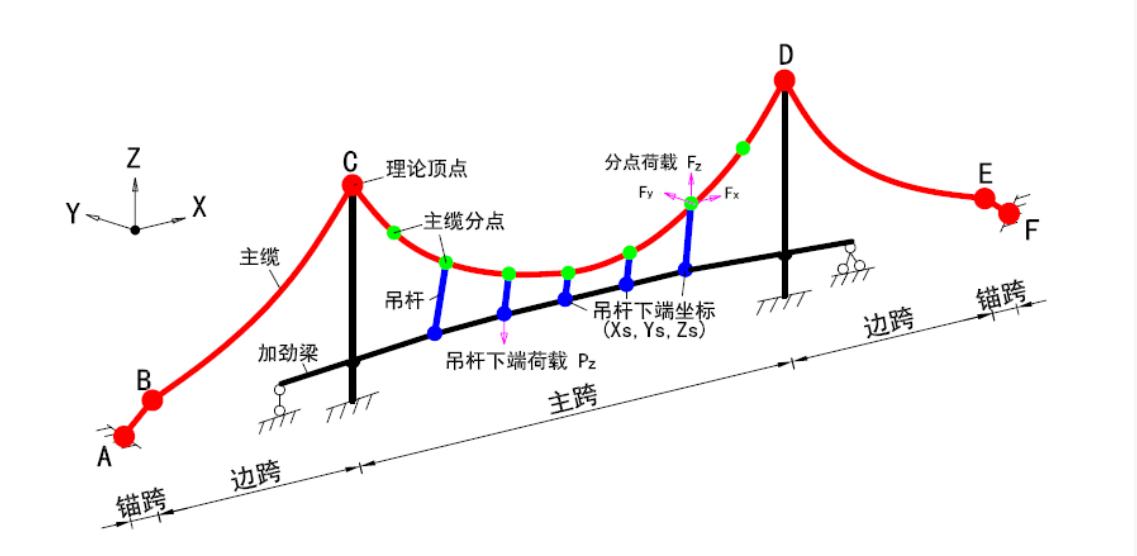
Overall coordinate axis settings are as shown in the figure: Bridge longitudinal direction is X-axis direction, taking rightward as positive; Bridge height direction is Z direction, taking upward as positive; Bridge transverse direction is Y direction, satisfying right-hand spiral rule with X and Z axes. All loads, displacements and internal force results take positive along coordinate axis forward direction, negative otherwise.
18.3 Basic Operations
Click main menu bar > Suspension Bridge Spatial Cable Shape > Full Bridge Data and Calculation. Enter spatial cable shape calculation window. In "Calculation Options and Types" page, select required calculation options, currently providing "Calculate Ideal Bridge Completion Cable Shape" (default mandatory), "Calculate Saddle Position", "Calculate Ideal Free Cable Shape" three calculation items.
18.3.1 Calculate Ideal Bridge Completion Cable Shape
The operation steps for calculating ideal bridge completion cable shape are as follows:
- Fill in various data in "Overall Information > Bridge Span Information" page and click Generate Bridge Spans button to generate bridge span information. In the case of already generated bridge span information, when modifying theoretical top point coordinates of each span, need to click this button again to update bridge span information, otherwise modification is invalid.
- Fill in various data of materials and sections in "Overall Information > Materials and Sections" page, and determine materials and sections of main cables for each span.
- Add main cable division points and hanger information for each span in "Main Cable Division Points and Hangers" page, and can preview division points and hanger positions.
- Fill in relevant data in "Stiffening Beam", "Hanger Cutting Length" pages as needed (default not filled).
- Click Calculate button to start calculation.
- If calculation is successful, can view relevant results in "Calculation Results" page.
- In the case of existing result data, must click Delete Results button before performing modification parameter operations.
18.3.2 Calculate Saddle Position Ideal Bridge Completion Cable Shape
The operation steps for calculating saddle position are as follows:
Besides filling data according to steps 1~4 of 18.3.1 calculating ideal bridge completion cable shape, also need to fill in detailed information of main cable saddle and side cable saddle in "Saddle Information" page, then start calculation.
18.3.3 Calculate Ideal Free Cable Shape
When calculating ideal free cable shape, must first calculate saddle position. The operation steps are as follows:
Fill in all data required for calculating saddle position. Besides this, also need to fill in information such as whether to change main cable properties, free cable calculation temperature difference, etc. in "Free Cable" page, then start calculation.
18.4 Full Bridge Data and Calculation Operation Interface Introduction
18.4.1 Basic Buttons
The functions of each basic button in the upper part of the window are as follows:
18.4.2 Overall Information—Bridge Span Information
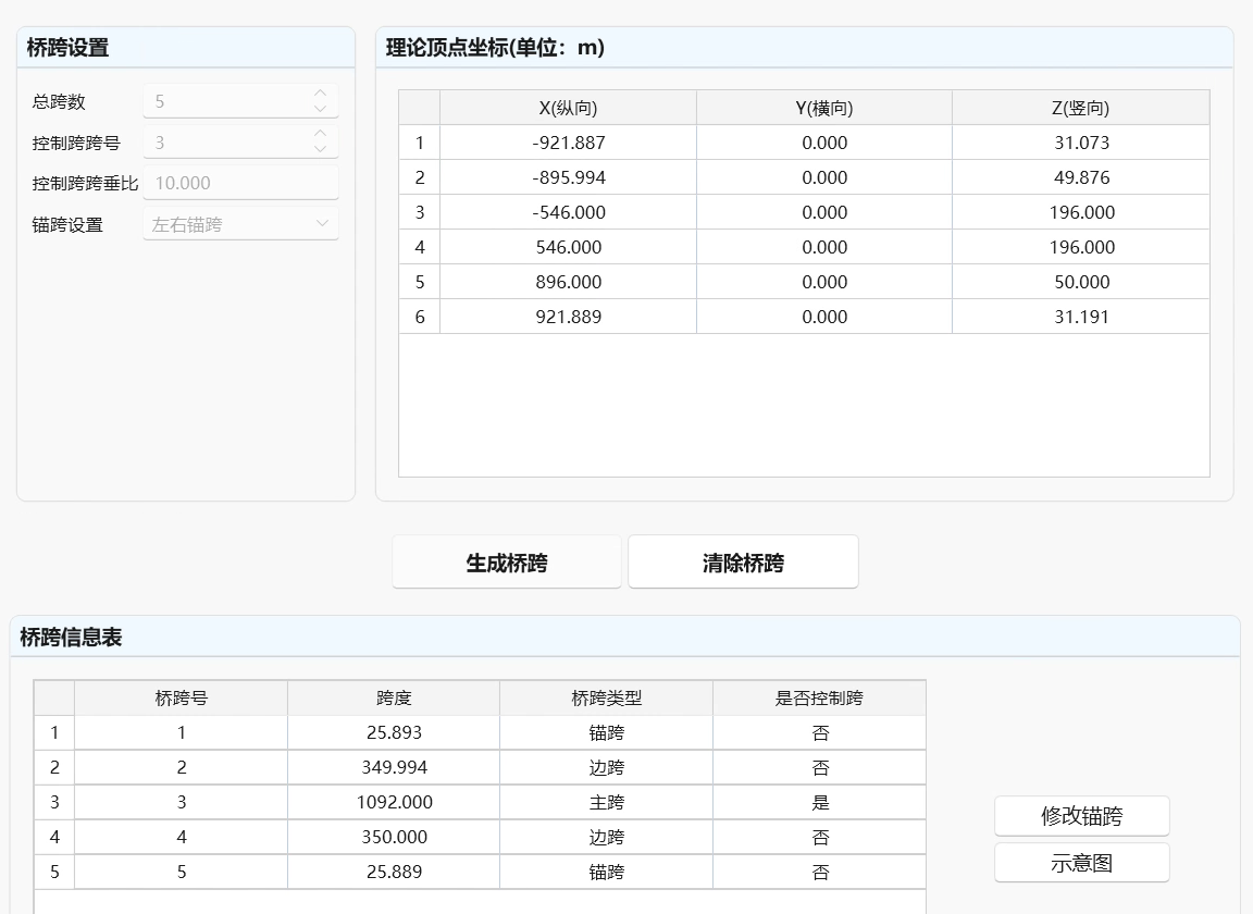
The bridge span information page is as shown in the figure:
-
Bridge Span Settings
Fill in total span count, control span number, control span sag ratio, whether anchor span exists.
-
Theoretical Top Point Coordinates of Each Span
Input X, Y, Z coordinates of each division point and anchor fixed point, click add button to add to the table on the right. Right-click and click delete to delete coordinates. Can directly paste data from other programs such as excel.
-
Generate/Update Bridge Span Information
Click this button. If there is no data error and no old bridge span information, bridge span basic information is successfully generated and displayed in "Bridge Span Information" table. In the case of already generated bridge span information, when modifying theoretical top point coordinates of each span, need to click this button again to update bridge span information, otherwise modification is invalid. Updating bridge span information will not modify materials, sections and division point information of main cables of each span, users should pay attention to check whether longitudinal coordinates of division points have exceeded span range causing calculation errors.
-
Clear Bridge Spans
When modifying overall data in the case of already generated bridge span information, for example X coordinates, anchor span settings, need to click this button to clear bridge span information first, before performing modification, to ensure overall data is consistent with bridge span information. Clearing bridge spans will lose all defined main cable division points, hanger and saddle information.
-
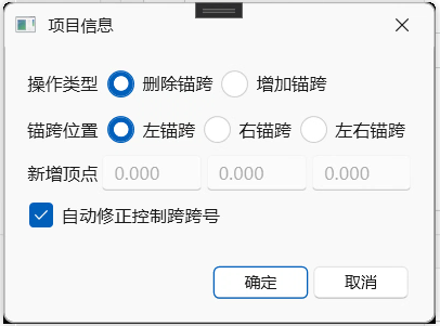
Modify Anchor Spans
A method provided by software to add or delete anchor spans, can preserve already defined side spans and main span main cable division points and hanger information.
-
Operation Type
Delete/Add anchor spans.
-
Anchor Span Position
Select to delete/add left anchor span, right anchor span, left and right anchor spans.
-
Add New Top Point
When adding left/right anchor spans, user needs to fill in top point coordinates of left/right anchor points.
-
Auto Correct Control Span Number
After checking this item, the program will automatically correct control span number according to bridge spans after deleting/adding anchor spans, to achieve the goal of not changing original control span. For example, original suspension bridge has 5 spans (spans 1 and 5 are left and right anchor spans), span 3 main span is control span. If deleting left anchor span, total span count becomes 4, main span becomes span 2. If checking this item, program automatically changes control span number to 2.
-
18.4.3 Sections and Materials
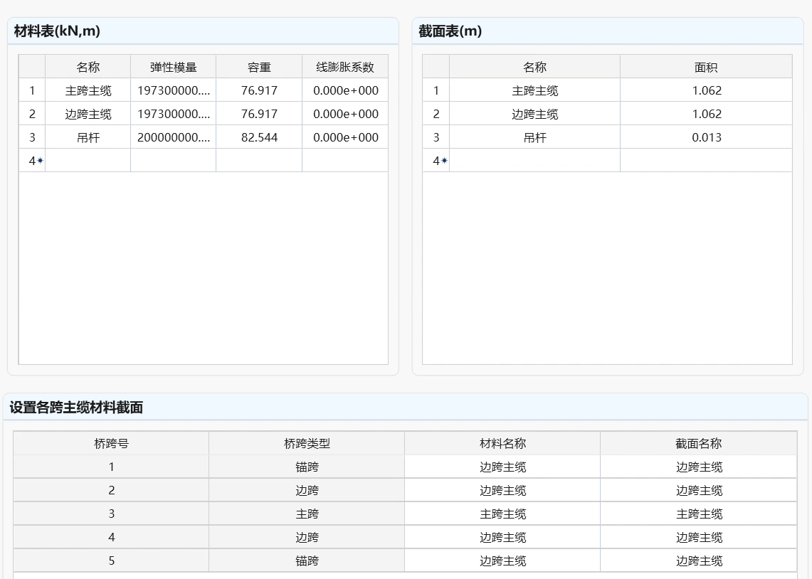
The sections and materials page is as shown in the figure:
-
Materials Table
Fill in names, elastic moduli, and unit weights of all materials.
-
Sections Table
Fill in names and areas of all sections.
-
Set Main Cable Material Sections for Each Span
Fill in materials and sections of main cables for each span, selecting from defined materials and section names.
18.4.4 Stiffening Beam Hangers
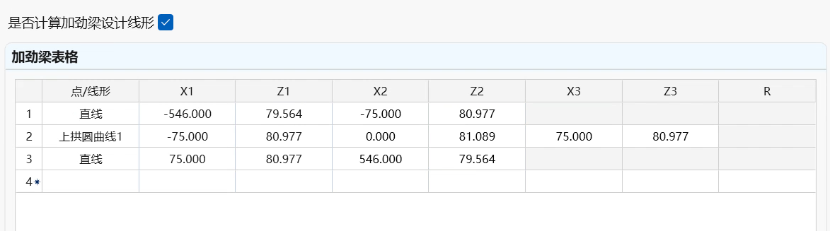
The stiffening beam hangers page is as shown in the figure:
-
Whether to Define Stiffening Beam Design Shape
User selects according to needs. If selecting yes, then D8_L, D8_R in hanger cutting length table, and hanger lower end coordinates Ys in main cable division point table are invalid. The program will automatically calculate these parameters according to user-defined stiffening beam design shape.
-
Stiffening Beam Design Shape Table
Shape types: including point, straight line, parabola, upper arch circular curve 1, upper arch circular curve 2, lower arch circular curve 1, lower arch circular curve 2, total 7 types. For parameters required to define various shapes, can refer to parameter description, as shown in the figure below.

X1, Z1/ X2, Z2/ X3, Z3: Horizontal and vertical coordinates of key points 1/2/3 defining stiffening beam shape. Radius: defines radius of stiffening beam shape (types 5 and 7 as shown in the figure below).
-
Whether to Calculate Hanger Cutting Length
User selects according to needs. If selecting yes, then fill in hanger cutting parameters according to bridge span number. Can refer to detailed parameter description according to hanger type (pin-hinged type or riding-over type).
-
Hanger Cutting Length Table
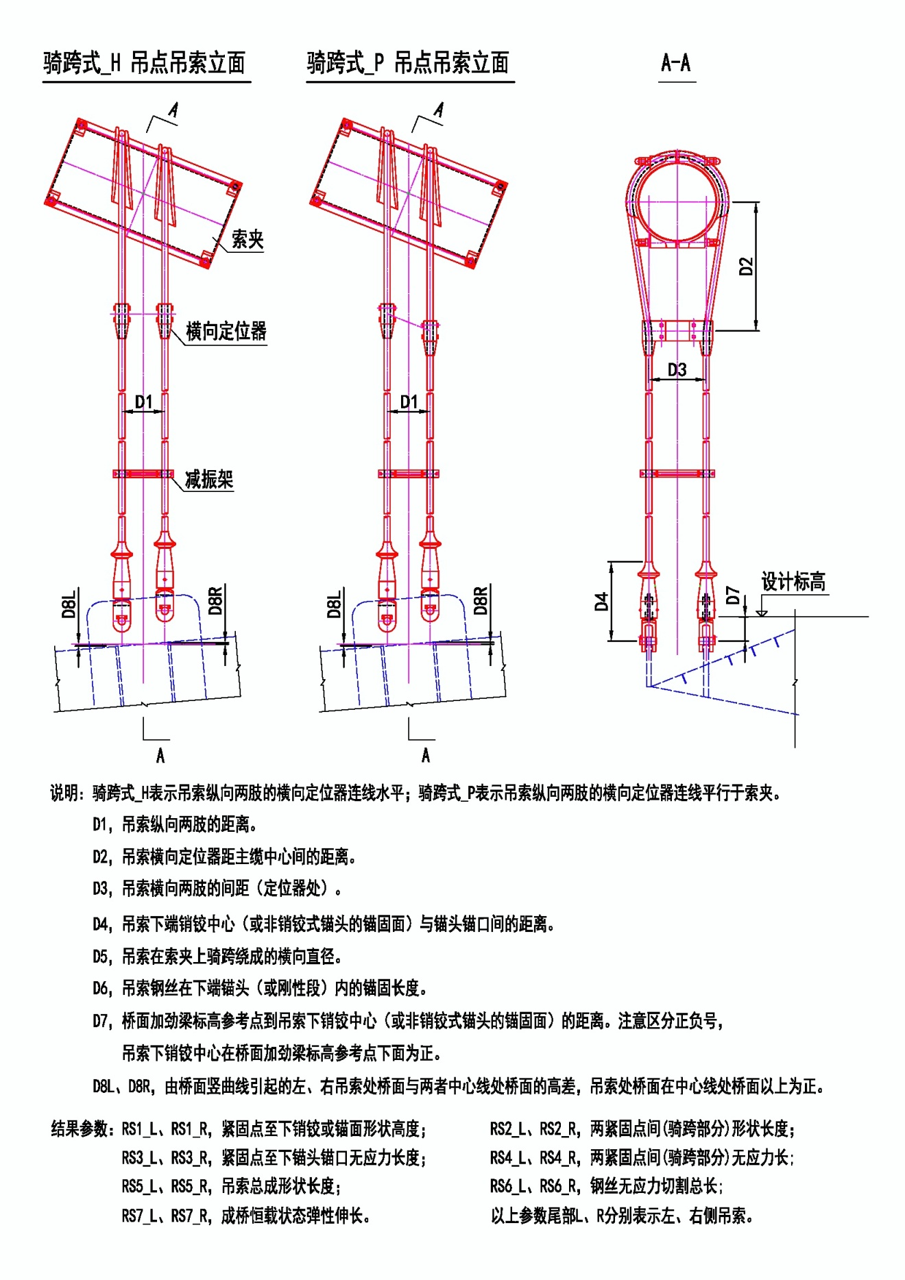
Types: including pin-hinged_H, pin-hinged_P, riding-over_H, riding-over_P, total 4 types. Among them, pin-hinged_H represents longitudinal two pin-hinge connection line horizontal; pin-hinged_P represents longitudinal two pin-hinge connection line parallel to cable clamps; riding-over_H represents transverse locator connection line of hanger cable longitudinal two limbs horizontal; riding-over_P represents hanger cable longitudinal two limbs transverse locator continuous parallel to cable clamps.
D1 Distance between hanger cable longitudinal two limbs D2 For pin-hinged_H: length from hanger upper pin-hinge center to main cable center; for pin-hinged_P: vertical distance from hanger upper pin-hinge center to main cable center. For riding-over type: distance from hanger transverse locator to main cable center. D3 For pin-hinged type: distance from hanger upper end pin-hinge center to anchor head anchor opening; for riding-over type: spacing between hanger cable longitudinal two limbs (at locator). D4 Distance from hanger lower end pin-hinge center (or non-pin-hinged type anchor head anchor surface) to anchor head anchor opening. D5 For pin-hinged type: anchor length of hanger steel wire inside upper end anchor head; for riding-over type: transverse diameter formed by hanger cable riding over at cable clamp. D6 Anchor length of hanger steel wire inside lower end anchor head (or rigid section). D7 Distance from bridge deck stiffening beam elevation reference point to hanger lower pin-hinge center (or non-pin-hinged type anchor head anchor surface). Note to distinguish positive and negative signs, when hanger lower pin-hinge center is below bridge deck stiffening beam elevation reference point, it is positive. D8L、D8R Height difference between bridge deck at hanger position and bridge deck at both centerlines caused by bridge deck vertical curve, when bridge deck at hanger position is above centerline bridge deck, it is positive. Pin-hinged hanger parameters and riding-over hanger parameters as shown in the diagram 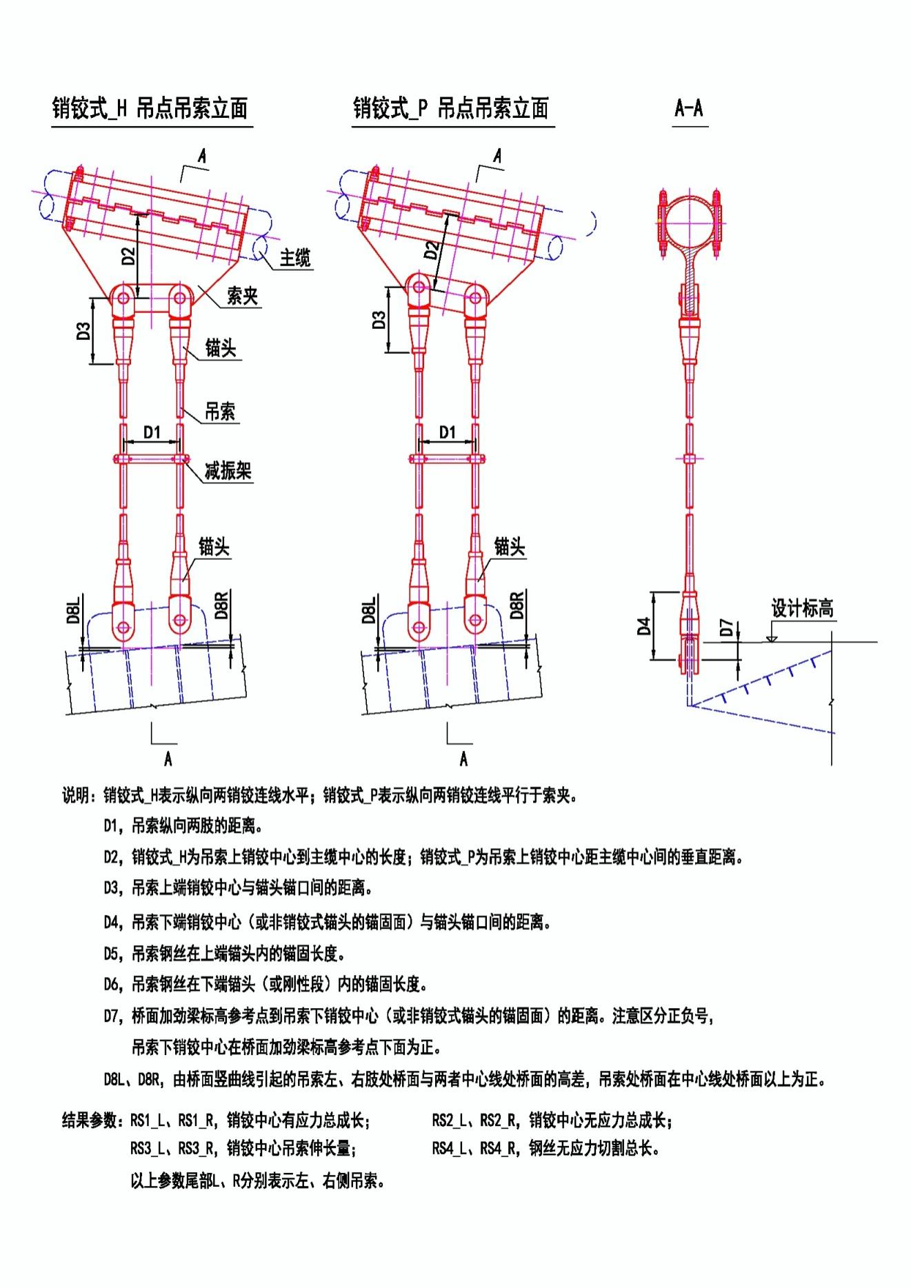
18.4.5 Main Cable Division Points
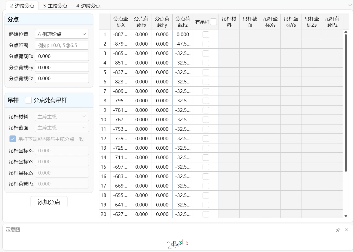
The program automatically generates main cable division points and hangers at division points according to bridge span number, starting position and division point distance, in order from left to right, as shown in the figure below.
-
Bridge Span Number
Select bridge span number for which to define main cable division points. If selected span is anchor span, prompts that division points cannot be added.
-
Starting Position
Left side theoretical point - default option. Calculate division point positions taking "left theoretical point" of that span as starting point.
Rightmost division point - taking the rightmost division point among all already added division points of that span as starting point to calculate division point positions.
-
Division Point Distance
Fill in distances between each division point. For example, 10,3@6.5 represents generating 4 division points, the 1st division point distance from starting position is 10m, the 2nd division point distance from the 1st division point is 6.5m, the 3rd division point distance from the 2nd division point is 6.5m, and so on.
-
Division Point Load
Fill in concentrated loads in x, y, z three directions at added division points.
-
Hanger Material
Fill in hanger material name at division point, selecting from defined materials.
-
Hanger Section
Fill in hanger section name at division point, selecting from defined sections.
-
Hanger Lower End Vertical Load
Fill in Z-direction vertical load borne by hanger lower end, direction taking upward as positive , therefore generally this item is negative value. If hanger does not exist, fill 0 for this item, or cancel "Has Hanger" item selection in hanger information table.
-
Lower End Coordinates
Fill in hanger lower end point coordinates.
-
Add Division Point
Click this button to add division point and hanger.
-
Clear All
Delete all main cable division points and hanger information of that span.
-
Delete Selected
Delete selected main cable division points and hanger information (need to click row header to select entire row).
-
Preview
Preview main cable division points and hanger positions of that span.
18.4.6 Saddles
The saddle page is as shown in the figure:
-
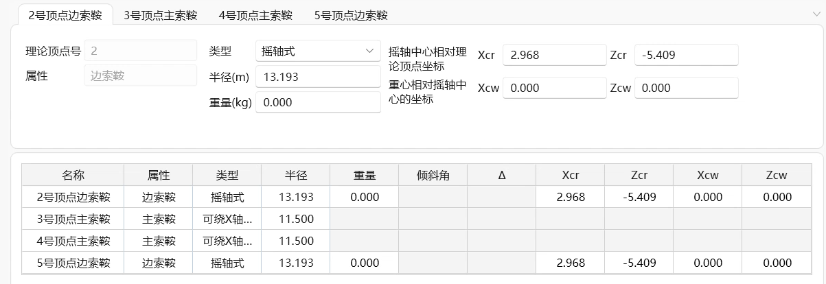
Cable Saddle Serial Number
After bridge span information is generated, the program automatically generates cable saddle serial numbers, names and saddle information table.
-
Type
Main cable saddle: includes non-rotatable, rotatable about X-axis, rotatable about Z-axis, rotatable about X and Z axes, four types.
Suspension cable saddle: includes sliding type and rocking shaft type, two types.
-
Saddle Data
Main cable saddle: input saddle radius.
Sliding suspension cable saddle: input saddle radius, weight, tilt angle. Tilt angle takes counterclockwise rotation as positive.
Rocking shaft suspension cable saddle: input saddle radius, weight, rocking shaft center coordinates relative to theoretical top point, center of gravity coordinates relative to rocking shaft center.
-
Edit Saddle
After filling in saddle data, click complete to modify.
18.4.7 Free Cable
The free cable page is as shown in the figure:
-
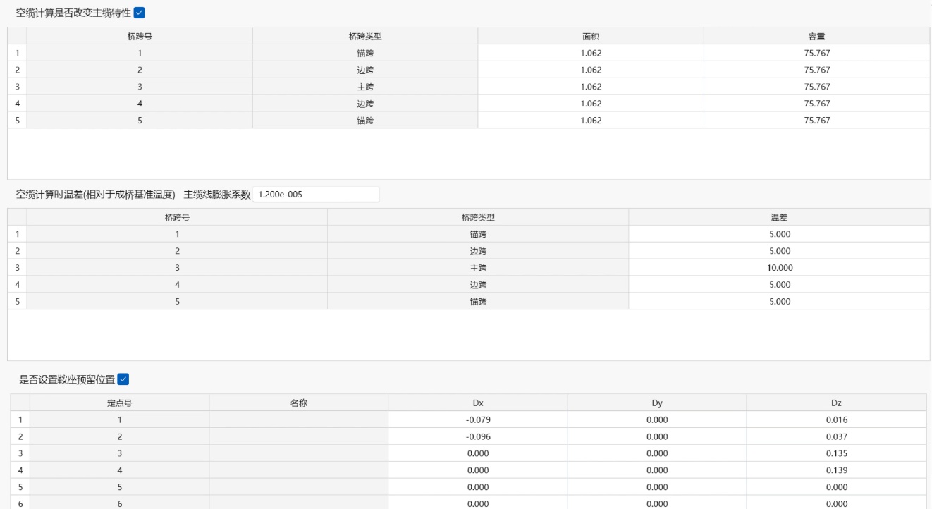
Whether to Change Main Cable Properties During Free Cable Calculation
Select yes or no according to needs. If yes, then fill in unit weight and section area of main cables for each span during free cable shape calculation.
-
Main Cable Material Linear Expansion Coefficient
Set main cable material linear expansion coefficient during free cable shape calculation.
-
Free Cable Temperature Difference
Set temperature difference of each span relative to reference temperature during free cable shape calculation.
-
Saddle Reserved Displacement Settings
Set reserved displacements of both anchor fixed points and each saddle during free cable shape calculation.
18.4.8 Calculation Settings
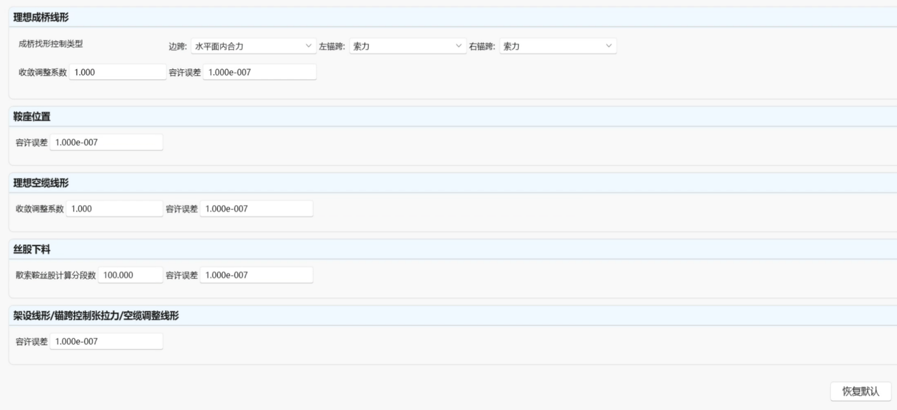
The calculation settings page is as shown in the figure:
Main Span Data and Main Cable Data
-
Bridge Completion Shape Finding Calculation Settings
Shape finding control force type: Can separately set shape finding control forces for side spans, left and right anchor spans. Side spans can select horizontal plane resultant force (equality), longitudinal force (equality) two items; anchor spans can select horizontal plane resultant force (equality), longitudinal force (equality), cable force (equality) three items.
Main cable iteration shape finding allowable error: Allowable error during bridge completion cable shape iterative calculation.
Convergence adjustment coefficient: Default value 1.0, when calculation cannot converge or convergence is slow, can appropriately increase or decrease this value to help calculation converge.
-
Saddle Position Calculation Settings
Whether to calculate saddle position: Select whether to consider saddle during bridge completion calculation.
Saddle iteration shape finding allowable error: Allowable error during bridge completion saddle iteration shape finding calculation.
-
Free Cable Shape Finding Calculation Settings
Whether to perform free cable calculation: If selecting yes, then should select calculate saddle position in saddle position calculation settings, otherwise cannot perform.
Main cable iteration shape finding and saddle preset amount allowable error: Allowable error during free cable iteration shape finding calculation.
Convergence adjustment coefficient: Default value 1.0, when calculation cannot converge or convergence is slow, can appropriately increase or decrease this value to help calculation converge.
18.4.9 Calculation Results
The calculation results page is as shown in the figure:
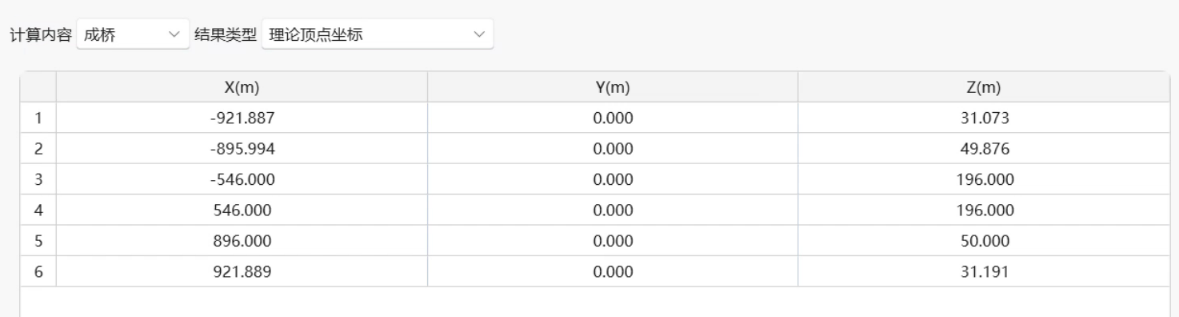
Query all calculation results through this page. Result types that can be queried are as follows:
| Calculation Content | Result Type | Description |
|---|---|---|
| Bridge Completion | Theoretical Top Point Coordinates | Coordinates of each theoretical top point (IP point) in bridge completion state. |
| Coordinates and Cable Forces in Each Span | Coordinates and left, right cable forces in each span in bridge completion state. | |
| Span End Forces | Span end forces of each span main cable in bridge completion state. | |
| Main Cable Division Point Information | Coordinates of main cable division points of each span in bridge completion state, vertical plane and horizontal plane internal tangent angles. | |
| Main Cable Segment Lengths | Unstressed length, elongation amount, and total curve length of main cable segments between division points of each span in bridge completion state. First and end points of each span main cable are IP points. | |
| Main Cable Segment End Forces | Left and right end forces of main cable segments between division points of each span in bridge completion state. | |
| Hanger Information | If "Calculate Hanger Cutting Length" is selected in "Stiffening Beam Hangers Page", then output result parameters according to hanger type (pin-hinged or riding-over) as follows: | |
| Pin-hinged type (parameters L, R at end represent left and right hangers): | ||
| RS1_L, RS1_R: Total stress growth at pin-hinge center. | ||
| RS2_L, RS2_R: Total unstressed growth at pin-hinge center. | ||
| RS3_L, RS3_R: Hanger elongation amount at pin-hinge center. | ||
| RS4_L, RS4_R: Total stress-free cutting length of steel wire. | ||
| Riding-over type (parameters L, R at end represent left and right hangers): | ||
| RS1_L, RS1_R: Height from anchor fixed point to lower pin-hinge or anchor head shape. | ||
| RS2_L, RS2_R: Shape length between two anchor fixed points (riding-over part). | ||
| RS3_L, RS3_R: Stress-free length from anchor fixed point to lower anchor head anchor opening. | ||
| RS4_L, RS4_R: Stress-free length between two anchor fixed points (riding-over part). | ||
| RS5_L, RS5_R: Total shape length of hanger cable. | ||
| RS6_L, RS6_R: Total stress-free cutting length of steel wire. | ||
| RS7_L, RS7_R: Elastic elongation in bridge completion constant load state. | ||
| If "Do Not Calculate Hanger Cutting Length" is selected in "Stiffening Beam Hangers Page", then output unstressed length, elongation amount, and total curve length of hangers of each span in bridge completion state. | ||
| Stiffening Beam Design Shape | Coordinates of stiffening beam nodes (corresponding to main cable division point positions in longitudinal direction) in bridge completion state. | |
| Modified Main Cable Length | Modified actual unstressed length, elongation amount, and total curve length of main cables of each span according to saddle fixed points (midpoints between saddle left and right cutting points). | |
| Saddle Groove Cable Segment Information | Unstressed cable length and total unstressed cable length on left and right sides of saddle fixed points. | |
| Saddle Position Information | Tilt angles, circle center coordinates, and actual top point coordinates of each saddle about X and Y axes in bridge completion state. | |
| Saddle Cutting Point Information | Coordinates of left and right cutting points of each saddle with main cable in bridge completion state, cutting point three-directional forces, vertical plane and horizontal plane internal tangent angles. | |
| Free Cable | Coordinates and Cable Forces in Each Span of Free Cable | Coordinates and left and right side cable force components of each span main cable in free cable state. |
| Main Cable Division Point Coordinates | Coordinates of main cable division points of each span in free cable state. | |
| Main Cable Division Point Forces | Left and right side division forces of main cable division points of each span in free cable state. | |
| Saddle Preset Amount | Saddle preset amounts of each span in free cable state. | |
| Free Cable Saddle Cutting Point Information | Coordinates of left and right cutting points and cutting point forces of each saddle in free cable state. | |
| Strand Cutting | Strand Cutting Length | Cutting length of each strand. |
| Whether Flat Bend is Within Vertical Bend | Whether flat bend of each strand at left and right spreading saddles is inside vertical bend point, 1 is yes, 0 is no. | |
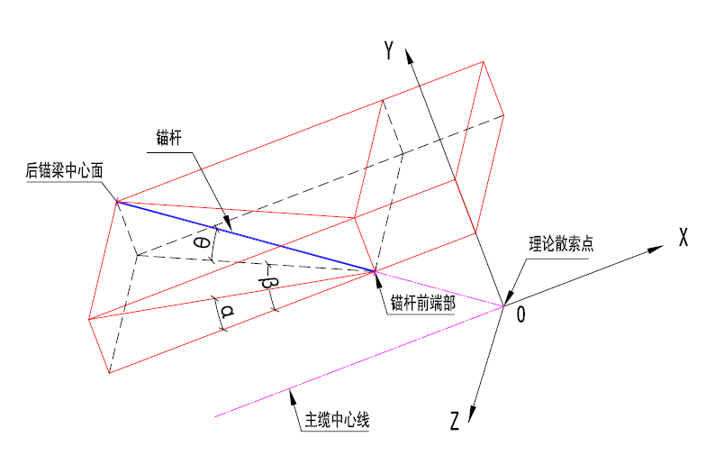
| Anchor Rod Length and Angle | Length and angle of left and right anchor rods of each strand. Anchor rod angle results include angle α between left and right anchor rod XY plane projection and main cable centerline, left and right anchor rod XZ plane projection and main cable centerline angle β, left and right anchor rod angle with XZ plane θ, see Figure 8-15. | |
| Strand Erection Theoretical Elevation | Erection elevation of strand strands at side and main span elevation control points. | |
| Strand Erection Shape | Strand Erection Theoretical Elevation in Span | Erection elevation of strand strands at points in side and main span. |
| Strand Cable Length Adjustment Amount | Unstressed length increment of strand strands. | |
| Strand Cable Shape | Each span shape of strand strands. | |
| Anchor Span Control Tension Force | Anchor Span Control Tension Force | Control tension force of left and right anchor spans of each strand. |
| Free Cable Adjustment Shape | Point Theoretical Elevation | Theoretical elevation of side and main span elevation control points after adjusted free cable shape. |
| Span Theoretical Elevation | Theoretical elevation of points in side and main span after adjusted free cable shape. | |
| Adjusted Free Cable Shape | Coordinates of main cable division points of each span after adjusted free cable shape, vertical plane and horizontal plane internal tangent angles. |