17. Stay Cable Intelligent Tensioning
17.1 Function Introduction
This module is based on intelligent optimization algorithms, using cable tension forces of each cable as design variables, and establishing an optimization model with constraints such as node displacements and element internal forces, performing optimization calculations to obtain ideal bridge completion cable forces (or cable lengths).
17.2 Basic Operations
17.2.1 Influence Matrix Generation
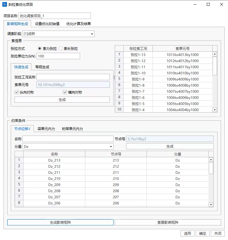
The influence matrix interface is as follows:
-
Tensioning Stage
Select the construction stage data model established:

-
Tensioning Method
Consistent with cable element tensioning method in construction stage;

-
Tensioning Cable Cases
There are two generation methods: quick generation and conventional generation:
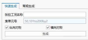
Quick generation method - Can frame select stay cable elements in 3D view, automatically generate stay cable tensioning cases based on whether longitudinal symmetry and transverse symmetry information;
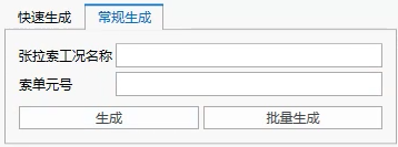
Conventional generation method - Need to manually generate each tensioning cable case. Can also directly perform add, modify, delete operations in tensioning cable cases;
-
Constraint Conditions
Node displacements Dx, Dy, Dz, Rx, Ry, Rz
Beam element internal forces IJ end Fx, Fy, Fz, Mx, My, Mz
Truss element IJ end axial internal forces
Node numbers and element numbers can be directly input, or selected in 3D view;
-
Generate Influence Matrix
Based on current interface information, tensioning stage, tensioning cable cases, and constraint conditions, automatically generate influence matrix;
-
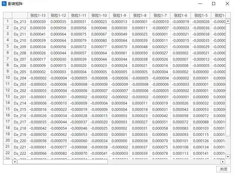
View Influence Matrix
Influence matrix columns are variation values of constraint conditions (node displacements, element internal forces) when unit force is tensioned for a certain tensioning cable case;
17.2.2 Set Optimization Initial Values
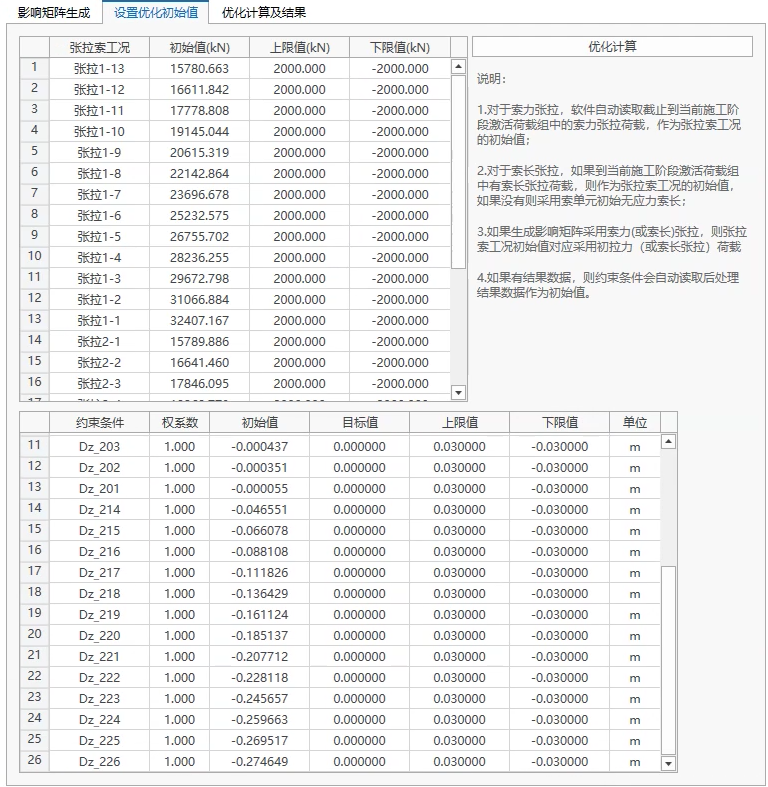
-
Tensioning Cable Cases
- Initial values: Software can automatically read tensioning cable case initial values based on model data For cable force tensioning, will automatically read cable force tensioning loads in load groups activated up to current construction stage; for cable length tensioning, if there are cable length tensioning loads in current activated load groups, they will be used as initial values of tensioning cases, if not, will use cable element initial unstressed cable length.
- Upper and lower limit values: Variation amount relative to initial values; Users can directly modify data in the table
-
Constraint Condition Initial Values
- Weight coefficient: Can fill 1 or 0, 1 represents considering this constraint condition, 0 represents not considering this constraint condition;
- Initial values: If there are calculation results, will automatically read constraint condition calculation results as initial values;
- Target values: Ideal target values
- Upper and lower limit values: Upper and lower limit values after constraint condition optimization; Example: For example, node vertical displacement, target value is 0.1m, upper limit value is 0.12m, lower limit value is 0.08m;
Users can directly modify data in the table
17.2.3 Optimization Calculation and Results
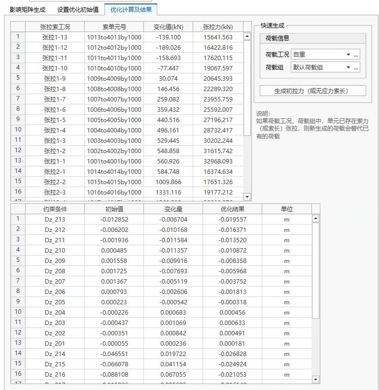
Results can view optimization variable values and final result values
Tensioning cable case optimization values can directly generate corresponding loads. If cable element cable forces (or cable length tensioning) already exist in load cases and load groups, newly generated loads will replace existing load values.