24. Wind-resistant Cable Shape-finding
Feature Introduction
This module is applicable to wind-resistant cables with parallel cable arrangement, wind-resistant cables with triangular cable crossing, spatial cable net structures, and other forms. It also supports traditional main cable shape-finding with inclined central clamps. Multiple control methods are supported to achieve precise and rapid solution of cable forces, cable lengths, and node coordinates. Main features include:
(1) Given the longitudinal force of the wind-resistant main cable and the tension of wind-resistant cables, calculate the horizontal and vertical coordinates of the wind-resistant main cable, etc.
(2) Given the mid-span horizontal coordinate of the wind-resistant main cable and the tension of wind-resistant cables, calculate the longitudinal force of the wind-resistant main cable, etc.
(3) Given the mid-span vertical coordinate of the wind-resistant main cable and the tension of wind-resistant cables, calculate the longitudinal force of the wind-resistant main cable, etc.
(4) Given the mid-span horizontal coordinate and longitudinal force of the wind-resistant main cable, calculate the tension of wind-resistant cables (uniform cable forces), etc.
(5) Given the mid-span vertical coordinate and longitudinal force of the wind-resistant main cable, calculate the tension of wind-resistant cables (uniform cable forces), etc.
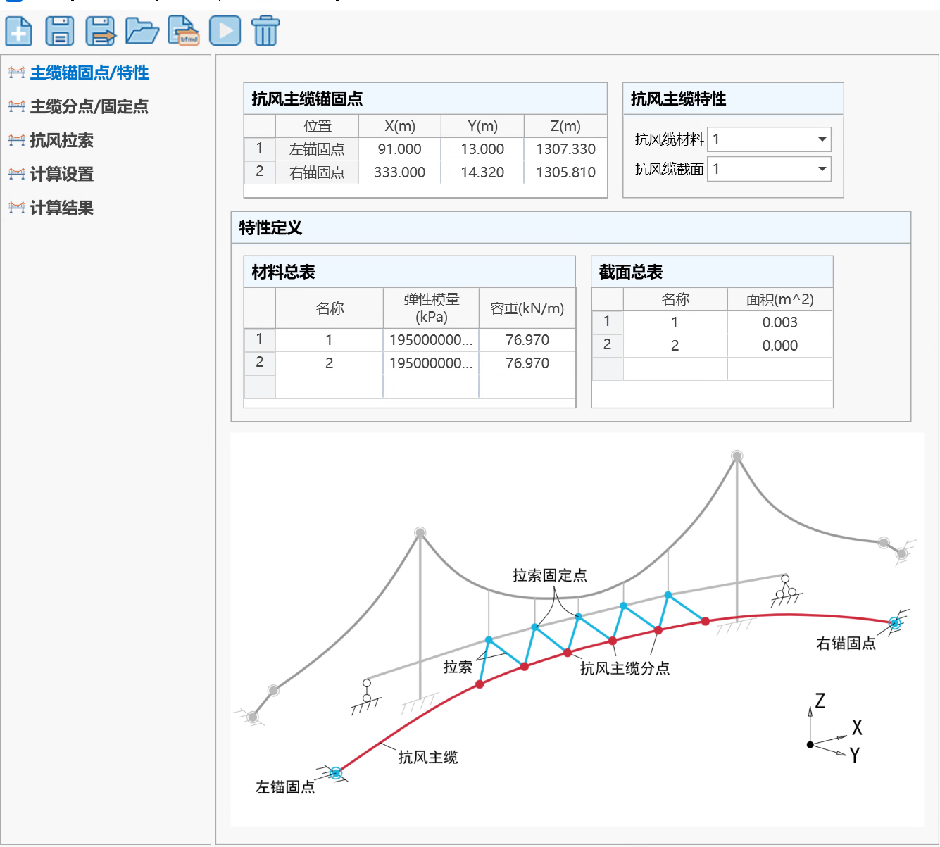
Unit System and Coordinate System
Unless otherwise specified, the unit system of this module is as follows: Force (kN), Length (m), Angle (°).
The global coordinate axes are set as shown below: The longitudinal direction of the bridge is the X-axis direction, with positive to the right; the height direction of the bridge is the Z-direction, with positive upward; the transverse direction of the bridge is the Y-direction, satisfying the right-hand rule with the X and Z axes. All loads, displacements, and internal force results are positive when along the positive direction of the coordinate axis, and negative otherwise.
Basic Operations
(1) Click the "Structure → Suspension Bridge Assistant → Wind-resistant Cable" icon to enter the module window;
(2) The homepage is the "Main Cable Anchor Points/Properties" page: Enter the main cable anchor point coordinates; in "Property Definition", input the cross-section and material property values of the main cable and cable elements; in "Wind-resistant Main Cable Properties", input the defined material and section names of the wind-resistant main cable.
(3) Enter the "Main Cable Nodes/Fixed Points" page: Add wind-resistant cable nodes and fixed points (nodes on the main girder).
(4) Enter the "Wind-resistant Cable Information" page: Define the endpoints of each wind-resistant cable (one end is the main cable node, the other is the fixed point), material name, and section name.
(5) Enter the "Calculation Settings" page: Define the shape-finding control method (two of the three quantities must be defined: wind-resistant cable longitudinal force, mid-span vertical/horizontal coordinates, cable force), set iteration precision (generally no modification needed).
(6) Click the "Calculate" button to start calculation.
(7) If calculation is successful, view related results on the "Calculation Results" page.
Calculation Interface Introduction
Basic Buttons

-
New: Create a new data file (*.sfmd1).
-
Save: Save data to the current project folder.
-
Save As: Save data to another path.
-
Open: Open other data files (*.sfmd1).
-
Export to QiaoTong: Export calculation results to the QiaoTong main program to generate corresponding elements, nodes, and loads.
-
Calculate: Click to start calculation.
-
Delete Results: Delete current result data.
Main Cable Anchor Points/Properties
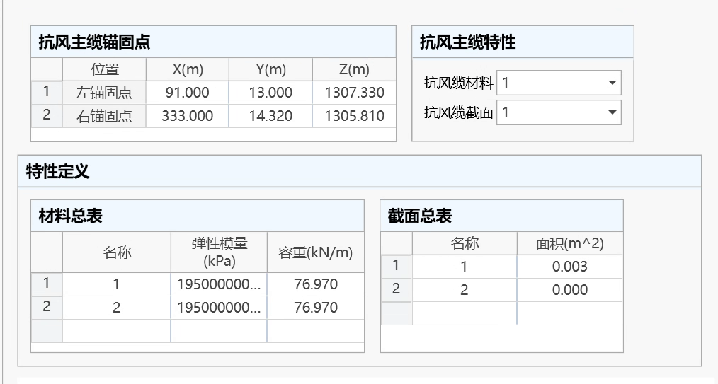
- Wind-resistant Main Cable Anchor Points
Enter the left and right endpoint coordinates of the wind-resistant cable.
- Materials
Enter the elastic modulus and unit weight of all materials.
- Sections
Enter the names and areas of all sections.
- Wind-resistant Main Cable Properties
Enter the material and section of the wind-resistant cable, selected from the defined material and section lists.
Main Cable Nodes/Fixed Points
The program automatically generates wind-resistant cable node positions, concentrated forces, and main girder node positions in left-to-right order based on the span number, starting position, and node spacing to determine the specific positions of wind-resistant cables.
Wind-resistant Cable Nodes
- Initial Position of Wind-resistant Cable Nodes
Left theoretical point — Default option. Calculate node positions starting from the "left theoretical point" of this span.
Rightmost node — Calculate node positions starting from the rightmost node among all added nodes in this span.
- Add Nodes
Enter the X-direction distance between nodes. For example, 10,3@6.5 means generating 4 nodes: the 1st node is 10m from the starting position, the 2nd node is 6.5m from the 1st node, the 3rd node is 6.5m from the 2nd node, and so on.
- Node Forces
Enter the concentrated loads in x, y, z directions at the added wind-resistant cable nodes.
- Clear All
Delete all wind-resistant cable nodes.
- Node Table
Display the X-coordinates and node forces of all added wind-resistant cable nodes, supporting table copy and paste. Right-click on the table to modify display precision.
Fixed Points
- Fixed Point Starting Coordinates
Enter the starting coordinates of fixed points (points on the main girder).
- Add Nodes
Enter the X-direction distance between fixed points.
- Clear All
Delete all fixed points.
- Node Table
Display the XYZ coordinates of all added fixed points, supporting table copy and paste. Right-click on the table to modify display precision.
Wind-resistant Cables
Define wind-resistant cables by entering the two endpoints of each cable (one end on the wind-resistant main cable, the other on the fixed point), as well as the cable's material and section in each row of the table.
Calculation Settings
- Calculation Method Settings
Select one of the 5 shape-finding control methods and enter the corresponding data according to the control method.
📌Note: You can set all cable force types uniformly through "Cable Force Type", or modify settings individually in the table.
- Shape-finding Iteration Error
The iteration error for shape-finding calculation, default is 1e-7. Users generally do not need to modify this.
- Convergence Adjustment Coefficient
When calculation convergence is difficult, this coefficient γ (0 < γ <= 1) can be adjusted appropriately to help convergence. Users generally do not need to modify this.
Calculation Results
View all calculation results through this page. The available result types are as follows:
| Calculation Content | Result Type | Description |
|---|---|---|
| Wind-resistant Cable Related | Main Cable Anchor Point Forces | Forces at both anchor points of the wind-resistant main cable in completed bridge state. |
| Main Cable Node Coordinates and Tangent Angles | Coordinates and vertical/horizontal tangent angles of each node of the wind-resistant main cable in completed bridge state. | |
| Main Cable Segment Lengths | Unstressed length, elongation, and total curve length of cable segments between main cable nodes in completed bridge state. | |
| Main Cable Segment End Forces | Left and right end forces of cable segments between main cable nodes in each span in completed bridge state. | |
| Cable Related | Cable Lengths | Unstressed length, elongation, and total curve length of cables in completed bridge state. |
| Cable End Forces | Forces at both ends (wind-resistant cable end and main girder end) of cables. | |
| Fixed Point Related | Vertical Reaction at Fixed Points | Vertical component of fixed point reactions. |