08. Boundaries
8.1 General Supports
-
Function: Constrain 6 degrees of freedom of nodes.
-
Commands:
"Main Menu" > "Boundaries" > "General Supports".
From the tree menu, select "Work" > "Boundaries" > "General Supports".
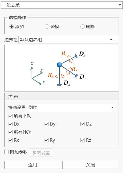
- Input
-
Boundary Group
Select the boundary group to which the general support belongs. By default, the "Boundary Default" group is selected. When you need to add and edit boundary groups, you can click the "..." button on the right to pop up the "Boundary Group Definition" dialog.
-
Selected Node Numbers
After clicking into the node number text box, select nodes in the model window to add general supports. You can also directly input node numbers.
-
Constrained Degrees of Freedom
D-ALL: All translational degrees of freedom.
Dx: Translational degree of freedom in the global coordinate system X-axis direction.
Dy: Translational degree of freedom in the global coordinate system Y-axis direction.
Dz: Translational degree of freedom in the global coordinate system Z-axis direction.
R-ALL: All rotational degrees of freedom.
Rx: Rotational degree of freedom about the global coordinate system X-axis direction.
Ry: Rotational degree of freedom about the global coordinate system Y-axis direction.
Rz: Rotational degree of freedom about the global coordinate system Z-axis direction.
-
Additional Parameters
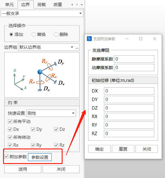
Additional parameters only take effect during construction stage calculation
(1) If the installation position in the construction stage is before deformation, the installation position of the general support adopts the initial displacement input in the additional parameters;
(2) If the installation position in the construction stage is after deformation, the general support is installed at the deformed position, and the additional parameters no longer take effect.
-
Operations
Add: Input a new general support.
Replace: Replace the previously input general support.
Delete: Delete the previously input general support.
-
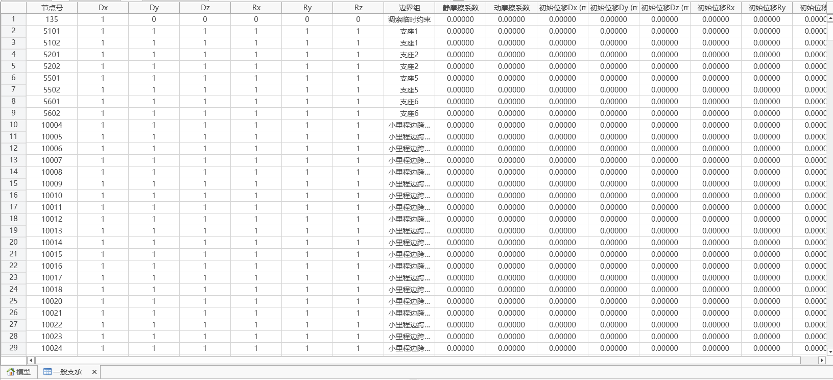
| Column Header | Property |
|---|---|
| Node Number | Node number |
| Dx | Constraint symbol for translational degree of freedom in global coordinate system X-axis direction |
| Dy | Constraint symbol for translational degree of freedom in global coordinate system Y-axis direction |
| Dz | Constraint symbol for translational degree of freedom in global coordinate system Z-axis direction |
| Rx | Constraint symbol for rotational degree of freedom about global coordinate system X-axis direction |
| Ry | Constraint symbol for rotational degree of freedom about global coordinate system Y-axis direction |
| Rz | Constraint symbol for rotational degree of freedom about global coordinate system Z-axis direction |
| Boundary Group | Name of the boundary group to which this general support belongs |
🧐The degree of freedom constraint symbol specifies 1 as constrained, 0 as unconstrained.
8.2 Elastic Supports
-
Function: Input spring stiffness to define elastic supports at nodes.
-
Commands:
"Main Menu" > "Boundaries" > "Elastic Supports".
From the tree menu, select "Work" > "Boundaries" > "Elastic Supports".
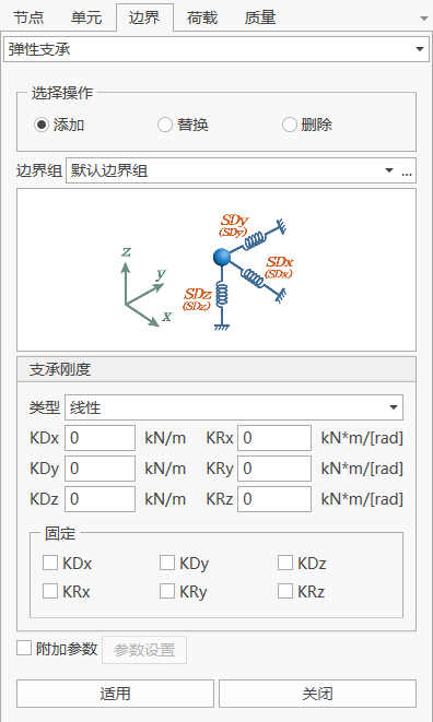
- Input
-
Boundary Group
Select the boundary group to which the elastic support belongs. By default, the "Boundary Default" group is selected. When you need to add and edit boundary groups, you can click the "..." button on the right to pop up the "Boundary Group Definition" dialog.
-
Selected Node Numbers
After clicking into the node number text box, select nodes in the model window to add elastic supports. You can also directly input node numbers.
-
Support Definition
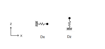
KDx: Elastic stiffness in the global coordinate system X-axis direction.
KDy: Elastic stiffness in the global coordinate system Y-axis direction.
KDz: Elastic stiffness in the global coordinate system Z-axis direction.
KRx: Elastic stiffness about the global coordinate system X-axis direction.
KRy: Elastic stiffness about the global coordinate system Y-axis direction.
KRz: Elastic stiffness about the global coordinate system Z-axis direction.
Among them, KDx, KDy, KDz can choose "Linear" (i.e., can be tension or compression), "Tension Only", "Compression Only" as three stiffness identifiers.
-
Direction
Based on node coordinate system
-
Additional Parameters
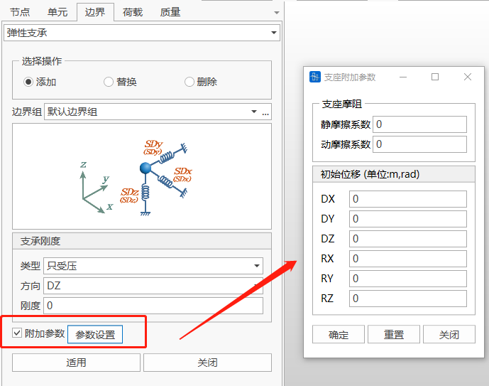
Additional parameters only take effect during construction stage calculation
(1) If the installation position in the construction stage is before deformation, the installation position of the general support adopts the initial displacement input in the additional parameters;
(2) If the installation position in the construction stage is after deformation, the general support is installed at the deformed position, and the additional parameters no longer take effect.
-
Operations
Add: Input a new elastic support.
Replace: Replace the previously input elastic support.
Delete: Delete the previously input elastic support.
-

| Column Header | Property |
|---|---|
| Node Number | Node number |
| Kx | Elastic support stiffness in global coordinate system X-axis direction (or defined node coordinate system x direction) |
| Ky | Elastic support stiffness in global coordinate system Y-axis direction (or defined node coordinate system y direction) |
| Kz | Elastic support stiffness in global coordinate system Z-axis direction (or defined node coordinate system z direction) |
| Krx | Rotational elastic support stiffness about global coordinate system X-axis (or defined node coordinate system x direction) |
| Kry | Rotational elastic support stiffness about global coordinate system Y-axis (or defined node coordinate system y direction) |
| Krz | Rotational elastic support stiffness about global coordinate system Z-axis (or defined node coordinate system z direction) |
| Boundary Group | Name of the boundary group to which this elastic support belongs |
8.3 General Elastic Supports
8.3.1 Define General Elastic Support Types
- Function: Input node general spring support stiffness. When a node local coordinate system is defined, the direction of degrees of freedom is the local coordinate system direction; otherwise, it's the global coordinate system direction.
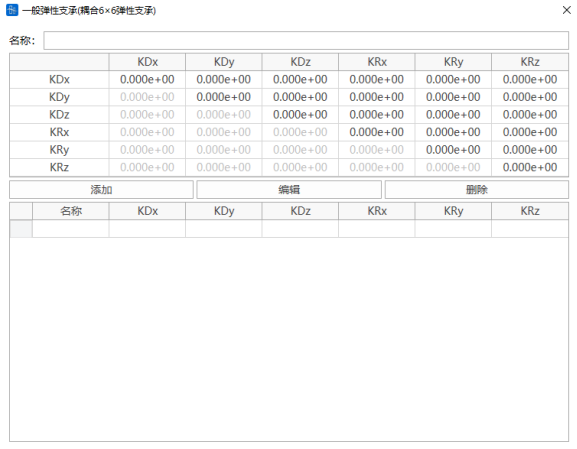
🧐The stiffness on the main diagonal elements needs to be greater than the stiffness of the non-diagonal elements in the row and column where the main diagonal element is located
8.3.2 General Elastic Supports
-
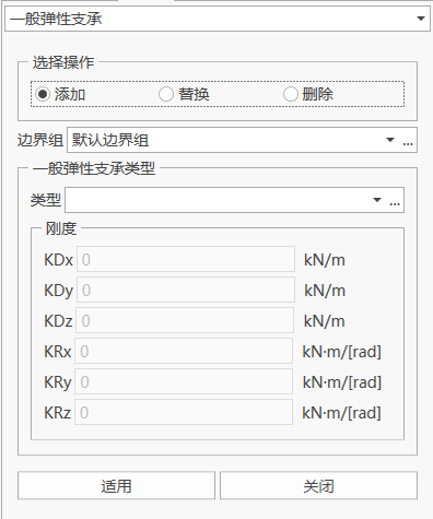
Function: Select general spring stiffness type to define general elastic supports at nodes
-
Commands:
"Main Menu" > "Boundaries" > "General Elastic Supports".
From the tree menu, select "Work" > "Boundaries" > "General Elastic Supports".
-
Boundary Group
Select the boundary group to which the elastic support belongs. By default, the "Boundary Default" group is selected. When you need to add and edit boundary groups, you can click the "..." button on the right to pop up the "Boundary Group Definition" dialog.
-
Selected Node Numbers
After clicking into the node number text box, select nodes in the model window to add general elastic supports. You can also directly input node numbers.
-
General Elastic Support Type
Select the general elastic support type. When you need to add and edit general elastic support types, you can click the "..." button on the right to pop up the "Define General Elastic Support Type" dialog.
8.4 Master-Slave Constraints
-
Function: Master-slave constraint function allows any degree of freedom of a certain node (slave node) to belong to another node (master node).
-
Commands:
"Main Menu" > "Boundaries" > "Master-Slave Constraints".
From the tree menu, select "Modeling Table" > "Boundaries" > "Master-Slave Constraints".
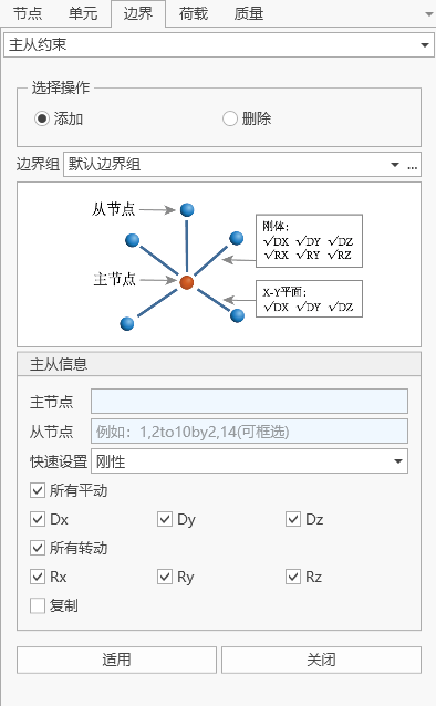
- Input
-
Boundary Group
Select the boundary group to which the master-slave constraint belongs. By default, the "Boundary Default" group is selected. When you need to add and edit boundary groups, you can click the "..." button on the right to pop up the "Boundary Group Definition" dialog.
-
Master-Slave Node Definition
Master Node Number: After clicking the mouse into the master node number text box, select nodes in the model window to add the master node. You can also directly input the master node number.
Slave Node Number: After clicking the mouse into the slave node number text box, select the slave node in the model window. You can also directly input the slave node number.
-
Constrained Degrees of Freedom
D-ALL: All translational degrees of freedom.
Dx: Translational degree of freedom in the global coordinate system X-axis direction.
Dy: Translational degree of freedom in the global coordinate system Y-axis direction.
Dz: Translational degree of freedom in the global coordinate system Z-axis direction.
R-ALL: All rotational degrees of freedom.
Rx: Rotational degree of freedom about the global coordinate system X-axis direction.
Ry: Rotational degree of freedom about the global coordinate system Y-axis direction.
Rz: Rotational degree of freedom about the global coordinate system Z-axis direction.
-
Copy
Direction: Global coordinate system X, Y, Z
Spacing: Copy interval, e.g., 1, 3@2.5, the number before @ is the count, and the interval distance after @
Note: There must be nodes at the copy position, otherwise the copy will not be successful
-
Operations
Add: Input a new master-slave constraint.
Delete: Delete the previously input master-slave constraint.
-
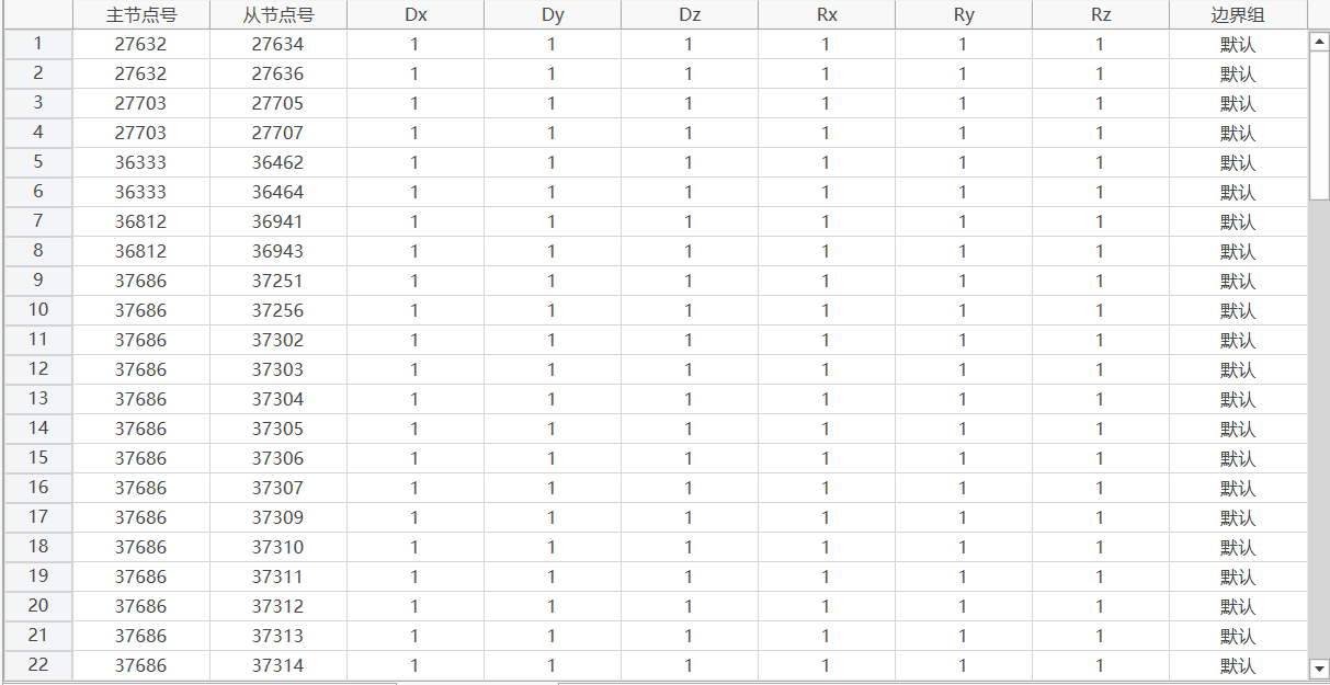
| Column Header | Property |
|---|---|
| Master Node Number | Master node number |
| Slave Node Number | Slave node number |
| Dx | Constraint symbol for translational degree of freedom in global coordinate system X-axis direction |
| Dy | Constraint symbol for translational degree of freedom in global coordinate system Y-axis direction |
| Dz | Constraint symbol for translational degree of freedom in global coordinate system Z-axis direction |
| Rx | Constraint symbol for rotational degree of freedom about global coordinate system X-axis direction |
| Ry | Constraint symbol for rotational degree of freedom about global coordinate system Y-axis direction |
| Rz | Constraint symbol for rotational degree of freedom about global coordinate system Z-axis direction |
| Boundary Group | Name of the boundary group to which this master-slave constraint belongs |
🧐The degree of freedom constraint symbol specifies 1 as constrained, 0 as unconstrained.
🧐The master node cannot serve as a slave node, the slave node cannot be a support element, and a certain degree of freedom of the slave node cannot belong to multiple degrees of freedom.
8.5 Elastic Links
-
Function: Create or delete elastic links. Two nodes are connected to form an elastic link.
-
Commands:
"Main Menu" > "Boundaries" > "Elastic Links".
From the tree menu, select "Modeling Table" > "Boundaries" > "Elastic Links".
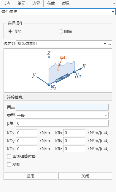
- Input
-
Boundary Group
Select the boundary group to which the elastic link belongs. By default, the "Boundary Default" group is selected. When you need to add and edit boundary groups, you can click the "..." button on the right to pop up the "Boundary Group Definition" dialog.
-
Type
General: General elastic link
Rigid: Rigid elastic link
Tension Only: Tension-only elastic link
Compression Only: Compression-only elastic link
-
Constraints
KDx: Translational degree of freedom in the element local coordinate system x-axis direction.
KDy: Translational degree of freedom in the element local coordinate system y-axis direction.
KDz: Translational degree of freedom in the element local coordinate system z-axis direction.
KRx: Rotational degree of freedom about the element local coordinate system x-axis direction.
KRy: Rotational degree of freedom about the element local coordinate system y-axis direction.
KRz: Rotational degree of freedom about the element local coordinate system z-axis direction.
-
Shear Spring Position
Input the position of the shear-type elastic support in the elastic link element. This item is mainly to consider the moment transmitted due to shear force at the two ends of the elastic support. When moments and shear forces act at the two ends of the elastic link, the moment is transmitted through the rotational stiffness of the elastic link, and the moment caused by the shear force is transmitted through calculation after defining the position of the shear-type elastic support.
Distance Ratio from I-end: Input the position of the shear-type elastic support in the local coordinate system y and z-axis directions (input as the ratio of the distance to the end point I).
(1) For general elastic links, the distance ratio can be set arbitrarily. If the shear spring position is not considered, the distance ratio from the I-end defaults to 0;
(2) For rigid elastic links, it automatically defaults to 0.5;
(3) For tension-only or compression-only links, the shear spring position is not set.
-
Notes
-
The installation method of elastic links in construction stages is all deformation method installation;
-
If the two points of the elastic link do not overlap, the elastic link uses its own coordinate system (same as beam elements); if the two points of the elastic link overlap, the elastic link coordinate system is consistent with the global coordinate system.
-
-
Operations
Add: Input a new elastic link.
Delete: Delete the previously input elastic link.
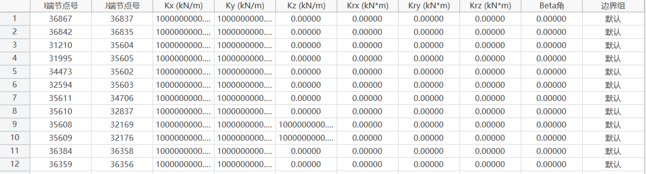
-
8.6 Constraint Equations
-
Function:
A constraint equation is a linear equation that relates degree of freedom values, with the following form:
Where U(I) is the degree of freedom term; Coefficient(I) is the coefficient of the degree of freedom term U(I); and N is the term number in the equation.
-
Commands:
"Main Menu" > "Boundaries" > "Constraint Equations".
From the tree menu, select "Modeling Table" > "Boundaries" > "Constraint Equations".
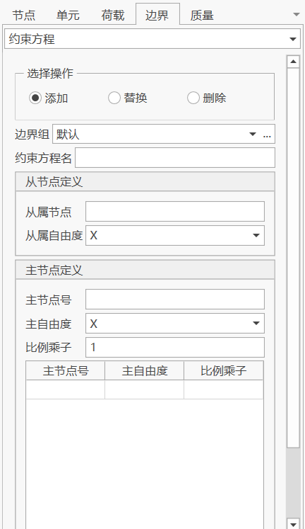
- Input
-
Boundary Group
Select the boundary group to which the constraint equation belongs. By default, the "Boundary Default" group is selected. When you need to add and edit boundary groups, you can click the "..." button on the right to pop up the "Boundary Group Definition" dialog.
-
Constraint Equation
Constant Term: Input the constant term of the constraint equation.
Node Count: The number of nodes included in the equation, i.e., the number of degree of freedom terms.
Master Node "…" Node 5: The node where the degree of freedom term is located. You can input directly or select by clicking to input.
-
Operations
Add: Add a constraint equation.
-
8.7 Release Beam End Constraints
-
Function: Add, modify, or delete beam end constraint releases.
-
Commands:
"Main Menu" > "Boundaries" > "Release Beam End Constraints".
"Main Menu" > "Boundaries" > "Boundary Table" > "Release Beam End Constraints".
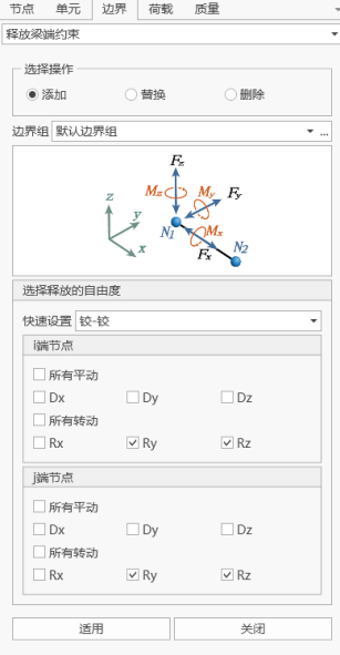
- Input
-
Boundary Group
Select the boundary group to which the constraint equation belongs. By default, the "Boundary Default" group is selected. When you need to add and edit boundary groups, you can click the "..." button on the right to pop up the "Boundary Group Definition" dialog.
-
Quick Settings
(1) Hinge—Hinge: Release the Ry and Rz degrees of freedom of the beam element I-end and J-end;
(2) Hinge—Rigid: Release the Ry and Rz degrees of freedom of the beam element I-end;
(3) Rigid—Hinge: Release the Ry and Rz degrees of freedom of the beam element J-end;
-
Release Degree of Freedom Selection
After checking the checkbox, it represents releasing that degree of freedom of the beam element.
-
Notes
(1) The I-end Dx and J-end Dx of the beam element can only release one. Similarly, the I-end Dy and J-end Dy, I-end Dz and J-end Dz, and I-end Rz and J-end Rz of the beam element can only release one.
(2) If the I-end Dx of the beam element is released, the I-end Ry and J-end Ry of the beam element can only release one.
(3) If the I-end Dy of the beam element is released, the I-end Rx and J-end Rx of the beam element can only release one.
-
8.8 Node Coordinate System
-
Function: Input or modify the node coordinate system of specified nodes.
-
Commands:
"Main Menu" > "Boundaries" > "Node Coordinate System".
"Main Menu" > "Boundaries" > "Boundary Table" > "Node Coordinate System".
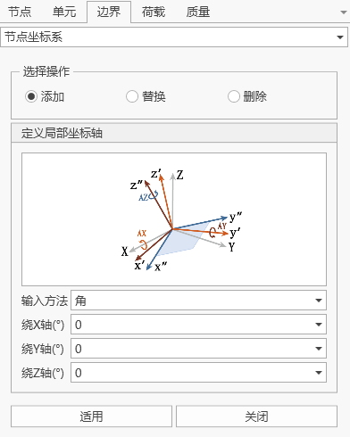
- Input
-
Node
Node number
-
Input Method (Angle)
Angle-X: Rotation angle about GCS X-axis.
Angle-Y: Rotation angle of the y' axis obtained by rotating about GCS X-axis.
Angle-Z: Rotation angle of the z" axis obtained by rotating about GCS X-axis and y' axis.
-
Input Method (Three Points)
P0-X, P0-Y, P0-Z: Coordinates of the origin point P0 in the global coordinate system.
P1-X, P1-Y, P1-Z: Coordinates of point P1 in the global coordinate system.
P2-X, P2-Y, P2-Z: Coordinates of point P2 in the global coordinate system.
-
Input Method (Vector)
V1-X: Component of vector V1 in the GCS X direction.
V1-Y: Component of vector V1 in the GCS Y direction.
V1-Z: Component of vector V1 in the GCS Z direction.
V2-X: Component of vector V2 in the GCS X direction.
V2-Y: Component of vector V2 in the GCS Y direction.
V2-Z: Component of vector V2 in the GCS Z direction.
-

🧐Notes (1) If a node coordinate system is defined at the node position of general supports and elastic supports, the support position automatically adopts the node coordinate system, and the output support reaction force is also the support reaction force under the node coordinate system. (2) For constraint equations and master-slave constraints, the node coordinate systems of related nodes need to be consistent. (3) If a certain node uses a node coordinate system, all boundaries, forced displacements, and settlements use the node coordinate system. (4) The coordinate system of node loads can be selected as "Node Coordinate System" or "Global Coordinate System". If a node coordinate system is set at the node position, and the node load coordinate system is selected as "Node Coordinate System", then the node load is the load under the node coordinate system; otherwise, node loads are under the global coordinate system. (5) Node displacement calculation results are under the global coordinate system.
8.9 Boundary Nonlinear Elements
8.9.1 Boundary Nonlinear Element Properties
-
Function: Define mechanical models for various nonlinear boundary elements.
-
Commands:
From the main menu, select "Loads" > "Dynamic Loads" > "Boundary Element Properties" > "Add".
From the tree menu, select "Boundary Conditions" > "Boundary Nonlinear Element Properties" > "Add" > "Type".
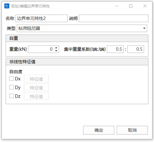
- Input
-
Name
Input the boundary nonlinear element property name
-
Type
Select the boundary nonlinear element type. Includes the following 5 types:

-
Self Weight
Input the total weight of the boundary nonlinear element. This weight is converted to node mass.
-
Concentrated Weight Coefficient
The proportion of the total element weight distributed to the I and J nodes.
-
Nonlinear Characteristic Values
Define characteristic values on the x, y, and z degrees of freedom.
🧐Note: Except for bearing friction damping and sliding friction pendulum, each element property can only define one direction characteristic value; bearing friction damping and sliding friction pendulum can define one axial and one tangential direction.
-
8.9.1.1 Hysteretic Damper
-
Mechanical formula:
Where F is the damping force, v is the velocity, C is the damping coefficient, and α is the velocity exponent.
-
Characteristic Value Definition:

Parameter Remarks Unit C Damping coefficient kN·(m/s)-α α Velocity exponent Dimensionless
8.9.1.2 Bearing Friction Damping
-
Mechanical formula:
Where F is the friction resistance force, Fy is the maximum friction resistance of the bearing, v is the tangential sliding velocity of the bearing, μ is the friction coefficient, P is the vertical bearing force of the bearing in the completed bridge state, K is the axial stiffness of the bearing, and u is the axial relative displacement of the bearing.
-
Characteristic Value Definition:


Parameter Remarks Unit K Bearing axial stiffness kN/m P Bearing support force in completed bridge state kN μ Bearing friction coefficient Dimensionless 🧐Note: The bearing axial stiffness K can be set to 0. When K is 0, it means that the variable axial force of the bearing is not considered, i.e., the maximum sliding friction force of the bearing is a constant value.
8.9.1.3 Sliding Friction Pendulum
-
Mechanical formula:
Where F is the friction force, Fy is the maximum friction force, v is the tangential sliding velocity of the friction pendulum, P is the friction pendulum support force in the completed bridge state, u2 is the tangential relative displacement of the friction pendulum, R is the curvature radius of the friction pendulum, μ is the friction coefficient, K is the axial stiffness of the bearing, and u1 is the axial relative displacement of the friction pendulum.
-
Characteristic Value Definition:

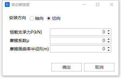
Parameter Remarks Unit K Friction pendulum axial stiffness kN/m P Support force in completed bridge state kN μ Friction coefficient Dimensionless R Friction pendulum curvature radius m 🧐Note: The sliding friction pendulum axial stiffness K can be set to 0. When K is 0, it means that the variable axial force in the axial direction is not considered, i.e., the maximum sliding friction force of the friction pendulum is a constant value.
8.9.1.4 Hook
-
Mechanical formula:
Where F is the internal force of the hook element, K is the elastic stiffness of the hook element, u is the relative displacement of the hook element, and o is the initial gap of the hook element.
-
Characteristic Value Definition:

Parameter Remarks Unit K Elastic stiffness kN/m o Initial gap m
8.9.1.5 Gap
-
Mechanical formula:
Where F is the internal force of the gap element, K is the elastic stiffness of the gap element, u is the relative displacement of the gap element, and o is the initial gap of the gap element.
-
Characteristic Value Definition:

Parameter Remarks Unit K Elastic stiffness kN/m o Initial gap m
8.9.2 Boundary Nonlinear Element Connection
-
Function: Create or delete boundary nonlinear elements. Two nodes are connected to form a boundary nonlinear element.
-
Commands:
"Main Menu" > "Loads" > "Dynamic Loads" > "Boundary Element Connection".
From the tree menu, select "Boundary Conditions" > "Time History Boundary" > "Add".
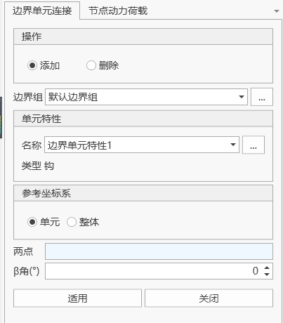
- Input
-
Operations
Select the Add button to create elements, and select the Delete button to delete elements.
-
Boundary Group
Select the boundary group to which the boundary nonlinear element belongs. By default, the "Default Boundary" group is selected. When you need to add and edit boundary groups, you can click the "..." button on the right to pop up the "Boundary Group Definition" dialog.
-
Element Properties
Select the defined boundary nonlinear element properties. When you need to add and edit element properties, you can click the "..." button on the right to pop up the "Boundary Element Properties" dialog to add and edit.
-
Reference Coordinate System
You can select the element local coordinate system and the structural global coordinate system. The degrees of freedom in the element properties will be determined according to this coordinate system.
-
Two Points
Select the two nodes at the I-end and J-end of the boundary nonlinear element.
-
Beta (β) Angle
The Beta (β) angle is used to define the z-direction of the boundary nonlinear element local coordinate system.
-
8.10 Boundary Groups
- Command: "Main Menu" > "Boundaries" > "Boundary Groups"
Several general supports, elastic supports, elastic links, and constraint equations form a boundary group, used to define the boundary conditions for each construction stage of the bridge. Boundary groups cannot have duplicate names.
8.11 Boundary Table
- Function: View and edit boundary information table, including general supports, elastic supports, master-slave constraints, elastic links, node coordinate systems, release beam end constraints, constraint equations, boundary nonlinear elements, and effective width amplification coefficients.
- Command: "Main Menu" > "Boundaries" > "Boundary Table"
Function: Add, modify, or delete beam end constraint releases.
8.2 Elastic Supports